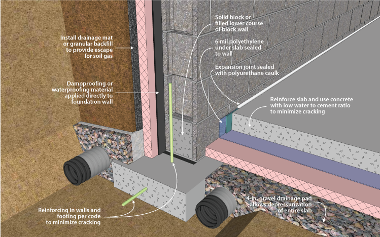
Figure 2-9F. Radon Control Techniques for Basements, Footing Detail
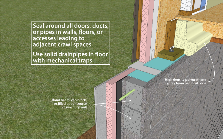
Figure 2-9S. Radon Control Techniques for Basements, Sill Detail
Construction techniques for minimizing radon infiltration into the basement are appropriate where there is a reasonable probability that radon may be present (see Figures 2-9s, 2-9f, and 2-10). To determine this, contact the state radon staff. General approaches to minimizing radon include (1) evacuating soil gas surrounding the basement, and (2) sealing joints, cracks, and penetrations in the foundation.
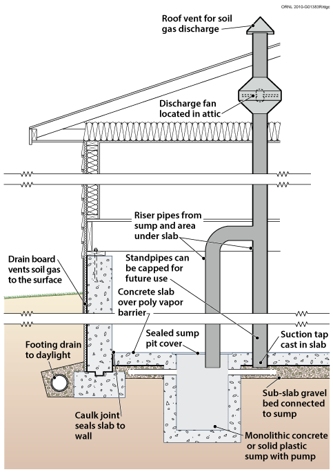
Figure 2-10. Soil Gas Collection and Discharge Techniques
The most effective way to limit radon and other soil gas entry is through the use of active soil depressurization (ASD). ASD works by lowering the air pressure in the soil relative to the indoors. Avoiding foundation openings to the soil, or sealing those openings, as well as limiting sources of indoor depressurization aid ASD systems. Sometimes a passive soil depressurization (PSD, with no fan) system is used. If post-occupancy radon testing indicates further radon reduction is desirable, a fan can be installed in the vent pipe (see Figure 2-10).
Subslab depressurization has proven to be an effective technique for reducing radon concentrations to acceptable levels, even in homes with extremely high concentrations (Dudney 1988). This technique lowers the pressure around the foundation envelope, causing the soil gas to be routed into a collection system, avoiding the inside spaces and discharging to the outdoors.
A foundation with good subsurface drainage already has a collection system. The underslab gravel drainage layer can be used to collect soil gas. It should be at least 4 inches thick, and of clean aggregate no less than 1/2 inch in diameter. The gravel should be covered with a 6-mil polyethylene radon and moisture retarder.
A 3- or 4-inch diameter PVC vent pipe should be routed from subslab gravel layer through the conditioned portion of the building and through the highest roof plane. The pipe should terminate below the slab with a “tee” fitting. To prevent clogging the pipe with gravel, ten-foot lengths of perforated draintile can be attached to the legs of the tee, and sealed at the ends. Alternately, the vent pipe can be connected to the perimeter drain system, as long as that system does not connect to the outdoor environment. Horizontal vent pipes could connect the vent stack through below grade walls to permeable areas beneath adjoining slabs. A single vent pipe is adequate for most houses with less than 2,500 square feet of slab area that also include a permeable subslab layer. The vent pipe is routed to the roof through plumbing chases, interior walls, or closets.
A PSD system requires the floor slab to be nearly airtight so that collection efforts are not short-circuited by drawing excessive room air down through the slab and into the system. Cracks, slab penetrations, and control joints must be sealed. Sump hole covers should be designed and installed to be airtight. Floor drains that discharge to the gravel beneath the slab should be avoided, but when used, should be fitted with a mechanical trap capable of providing an airtight seal.
Another potential short circuit can occur if the subdrainage system has a gravity discharge to an underground outfall. This discharge line may need to be provided with a mechanical seal. The subsurface drainage discharge line, if not run into a sealed sump, should be constructed with a solid-glued drainpipe that runs to daylight. The standpipe should be located on the opposite side from this drainage discharge.
While a properly installed passive soil depressurization (PSD) system may reduce indoor radon concentrations by about 50%, active soil depressurization (ASD) systems can reduce indoor radon concentrations by up to 99%. A PSD system is more limited in terms of vent pipe routing options, and is less forgiving of construction defects than ASD systems. Furthermore, in new construction, small ASD fans (25-40 watt) may be used with minimal energy impact. Active systems use quiet, in-line duct fans to draw gas from the soil. The fan should be located outside, and ideally above, the conditioned space so that any air leaks from the positive pressure side of the fan or vent stack are not in the living space. The fan should be oriented to prevent accumulation of condensed water in the fan housing. The ASD stack should be routed up through the building or an attached garage or carport, and extend twelve inches above the roof. It can also be carried out through the band joist and up along the outside of wall, to a point high enough so that there is no danger of the exhaust being redirected into the building through attic vents or other pathways. Because PSD systems rely on natural buoyancy to operate, a PSD stack must be routed through the conditioned portion of the home.
A fan capable of maintaining 0.2 inch of water suction under installation conditions is adequate for serving subslab collection systems for most houses (Labs 1988). This is often achieved with a 0.03 hp (25W), 160 cfm centrifugal fan (maximum capacity) capable of drawing up to 1 inch of water before stalling. Under field conditions of 0.2 inch of water, such a fan operates at about 80 cfm.
It is possible to test the suction of the subslab system by drilling a small (1/4-inch) hole in areas of the slab remote from the suction point, and measuring the suction through the hole using a micromanometer or inclined manometer. The goal of a subslab depressurization system is to create negative air pressure below the slab, relative to the air pressure in the adjacent interior space. A suction of 5 Pascals is considered satisfactory when the house is placed in a worst-case depressurization condition (i.e., house closed, all exhaust fans and devices operating, and with the HVAC system operating with interior doors shut). The hole must be sealed after the test.
PSD systems require near perfection in sealing of openings to the soil, since the system relies on a 3- or 4-inch pipe to vent more effectively than the entire house. Sealing openings to the soil is less critical for radon control with ASD systems, although it is highly desirable in order to limit the energy penalty associated with conditioned indoor air leaking into a depressurized subslab, and from there to the outdoors. ASD fans have service lives averaging about ten years, with a higher life expectancy if the fan is protected from the elements. Since an ASD system may be turned off by occupants, service switches are usually located in areas with limited access.
For more information visit Water Managed Foundations within the Building America Solution Center.

