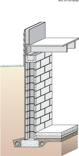
Figure 2-1. Concrete Masonry Basement Wall with Exterior Insulation
STRUCTURAL DESIGN
The major structural components of a basement are the wall, the footing, and the floor (see figure 2-2). Basement walls are typically constructed of cast-in-place concrete or concrete masonry units. Basement walls must be designed to resist lateral loads from the soil and vertical loads from the structure above. The lateral loads on the wall depend on the height of the fill, the soil type, soil moisture content, and seismic activity. Because of the large number of variables involved in foundation structural design, final determination of wall thickness, concrete strength, footing dimensions, and reinforcing should be made after consultation of locally-enforced building codes or design by a licensed structural engineer.
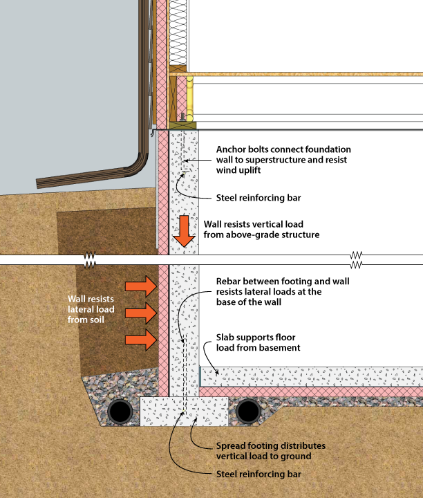
Figure 2-2. Structural System Components of a Basement
Concrete spread footings provide support beneath basement concrete and masonry walls and columns. Footings must be designed with adequate size to distribute the load to the soil. Freezing water beneath footings can heave, causing cracking and other structural problems. Unless founded on bedrock or proven non-frost-susceptible soils, footings must be placed beneath the maximum frost penetration depth or be insulated to prevent frost penetration.
Concrete slab floors are generally designed to have sufficient strength to support floor loads without reinforcing when poured on undisturbed or compacted soil. The use of welded wire fabric and concrete with a low water/cement ratio can reduce shrinkage cracking, which is an important concern for appearance and for reducing potential radon infiltration. The slab should be poured against a control joint material so that it can move independently of the foundation wall. Where expansive soils are present or in areas of high seismic activity, special foundation construction techniques may be necessary. In these cases, consultation with local building officials and a structural engineer is recommended.
In general, moisture management schemes must control water in two states. First, since the soil in contact with the foundation wall is always at 100% relative humidity, foundation walls must deal with water vapor that will tend to migrate toward the interior under most conditions. Second, liquid water entry must be prevented. Liquid water can enter from sources such as:
Techniques for controlling the build-up of moisture in the basement wall assemblies are an essential component of the overall construction. Improper moisture management can lead to structural damage, damage to finishes or basement contents, and mold growth, which can be very costly to repair and hazardous to one's health.
The following construction practices will prevent excess water in the form of liquid water and vapor from infiltrating the basement. This is done by using adequate drainage and by the use of vapor retarders as shown in Figures 2-3F and 2-3S.
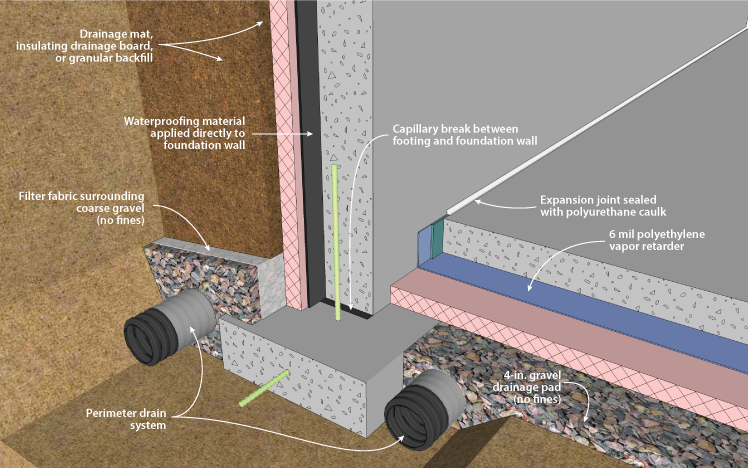
Figure 2-3F. Drainage and Waterproofing System Components in a Basement, Footing Detail
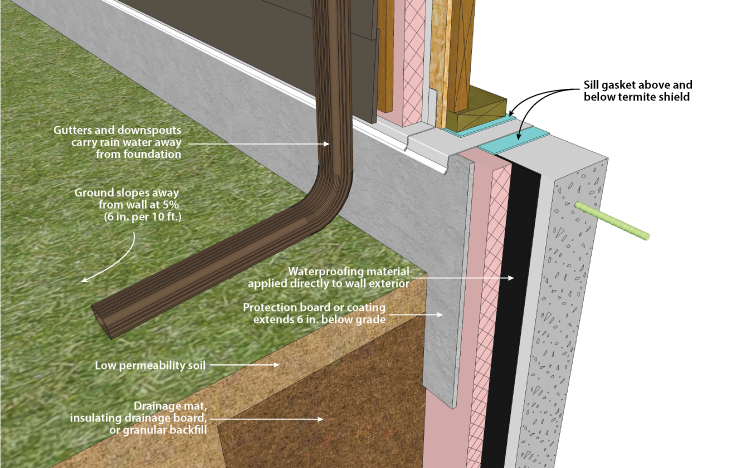
Figure 2-3S. Drainage and Waterproofing System Components of a Basement, Sill Detail
Concrete foundation walls contain water from when they were poured which needs to be dissipated by allowing them to dry. In cases where the majority of the wall is below grade, it can only dry to the interior. The insulation material and the wall covers placed on the walls during the construction of the crawl space act as vapor retarders, not allowing the walls to dry to the interior. For this reason, it is recommended that these wall coverings be installed near the end of construction to allow for as much drying of the concrete as possible (BSC 2006).
In basement spaces it is important not only to have an effective vapor retarder, but also to have a complete air barrier. For this reason, all gaps between the foundation wall and sill plate, sill plate and band joist, and band joist and subfloor should be sealed. All gaps and penetrations in the foundation wall also need to be adequately sealed.
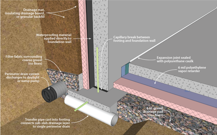
Figure 2-4. Drainage and Waterproofing System Components in a Basement (Single Perimeter Drain System), Footing Detail
Keeping water out of basements is a major concern in many regions. The source of water is primarily from rainfall, snow melt, and sometimes irrigation on the surface. In some cases, the groundwater table is near or above the basement floor level at times during the year. There are three basic lines of defense against water problems in basements: (1) surface drainage, (2) subsurface drainage, and (3) waterproofing on the wall surface (see Figures 2-3F, 2-3S, and 2-4).
The goal of surface drainage is to keep water from surface sources away from the foundation by sloping the ground surface and using gutters and downspouts for roof drainage. Subsurface drainage systems intercept, collect, and carry away any water in the ground surrounding the basement. Components of a subsurface system can include porous backfill, drainage mat materials or insulated drainage boards, and perforated drainpipes in a protected gravel bed along the footing or beneath the slab that drain to a sump or to daylight. Local conditions will determine which of these subsurface drainage system components, if any, are recommended for a particular site.
Figure 2-3F shows a dual drain system, which is the most robust option. Figure 2-4 shows a single-drain configuration. In both cases, provision is made to drain water originating at the surface that drains down along the foundation, as well as water that may accumulate under the slab. Figure 2-3F shows the best practice system for foundation perimeter drainage. It consists of two independent loops of perforated foundation drain, one inside the footing and one outside. These drain independently, either to daylight or to an internal sump. Figure 2-4 shows another option that is appropriate when site drainage conditions are good. It also allows drainage of the sub-slab gravel layer, through ducts that run through the bottom of the footing. These ducts should be placed as close to the bottom of the footing as possible, to avoid water pooling on the inside of the footing. Its single loop of foundation drain is on the outside of the footing, and drains to daylight or to an internal sump. It should be noted that the duct connection to the exterior of the footing can reduce the effectiveness of subslab depressurization radon mitigation systems by reducing the ability of the system to maintain sufficiently low pressures beneath the slab.
The final line of defense— waterproofing—is intended to keep out water that finds its way to the wall of the structure. First, it is important to distinguish between the need for dampproofing versus waterproofing. In most cases a dampproof coating covered by a 4-mil layer of polyethylene is recommended to reduce vapor and capillary draw transmission from the soil through the basement wall. A dampproof coating, however, is not effective in preventing water under hydrostatic pressure from entering through the wall. Waterproofing is recommended (1) on sites with anticipated water problems or poor drainage, (2) when finished basement space is planned, or (3) on any foundation built where intermittent hydrostatic pressure occurs against the basement wall due to rainfall, irrigation, or snow melt. Except on very dry sites, it is generally recommended to use waterproofing as a best practice. On sites where the basement floor could be below the water table, a crawl space or slab-on-grade foundation is recommended.
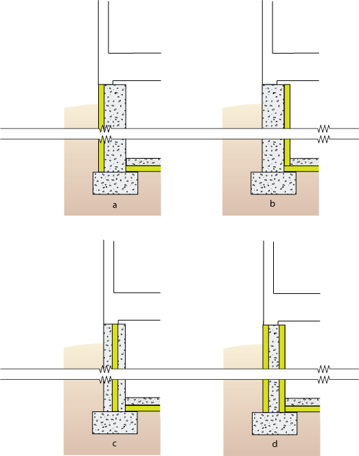
Figure 2-5. Potential Locations for Basement Insulation
A key question in foundation design is whether to place insulation on the inside or outside surface of the basement wall (Figure 2-5). In terms of energy use, there is not a significant difference between the same amount of full wall insulation applied to the exterior versus the interior of a concrete or masonry wall. However, the installation costs, ease of application, appearance, and various technical concerns can be quite different. Individual design considerations as well as local costs and practices determine the best approach for each project.
Rigid insulation placed on the exterior surface of a concrete or masonry basement wall has some advantages over interior placement in that it (1) can provide continuous insulation with no thermal bridges, (2) protects and maintains the waterproofing and structural wall at moderate temperatures, (3) minimizes moisture condensation problems, and (4) does not reduce interior basement floor area (Figure 2-6). If the exterior insulation extends up to cover the rim, and its R-value is high enough, the joists and sill plates can be left open to inspection from the interior for termites and decay. On the other hand, exterior insulation on the wall can provide a path for termites if not treated adequately and can prevent inspection of the wall from the exterior. Insulation that is exposed above grade must be protected with a coating to prevent physical damage and degradation. Such coatings include fiber cement board, parging (stucco type material), treated plywood, or membrane material (Baechler et al. 2005). Exterior insulation places the foundation wall within the thermal envelope. This means the wall will be warmer in winter, and moisture is free to dry to the interior. Because of this, impermeable materials like oil paint, polyethylene, or vinyl wallpaper should not be used as interior finishes.
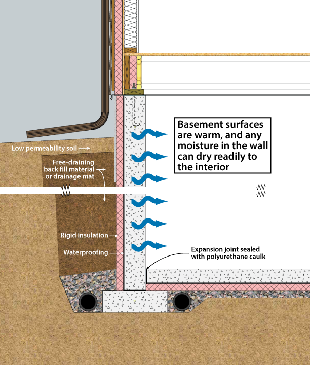
Figure 2-6. Basement with Exterior XPS or EPS insulation
Exterior wall insulation must be approved for below-grade use. Typically, three products are used below grade: extruded polystyrene, expanded polystyrene, and rigid mineral fiber panels. (Baechler et al. 2005). Extruded polystyrene (nominal R-5 per inch) is a common choice. Expanded polystyrene (nominal R-4 per inch) is less expensive, but it has a lower insulating value. Below-grade foams can be at risk for moisture accumulation under certain conditions. Experimental data indicate that this moisture accumulation may reduce the effective R-value as much as 35%-44%. Research conducted at Oak Ridge National Laboratories studied the moisture content and thermal resistance of foam insulation exposed below grade for fifteen years; moisture may continue to accumulate and degrade thermal performance beyond the fifteen-year time frame of the study. This potential reduction should be accounted for when selecting the amount and type of insulation to be used (Kehrer, et al., 2012, Crandell 2010).
Rigid fiberglass and rigid mineral wool panels (R-4 per inch) do not insulate as well as extruded polystyrene, but are the only insulations that can provide a drainage space for foundation walls because of their porous structure. Use of these materials as a drainage space only works if effective footing perimeter drains are present.
Unfortunately, insulating the exterior is more difficult and more costly than insulating the foundation internally; this is particularly true in retrofit applications. For this reason, interior insulation is most commonly used. However, actual costs may be higher if a finished, durable surface is desired. In addition, foam insulation materials will require a flame-resistant layer for code compliance. Energy savings may be reduced with some systems and details due to thermal bridges. Insulation can be placed on the inside of the rim joist but with greater risk of condensation problems and less access to wood joists and sills for termite inspection from the interior. Interior insulation systems are not recommended for concrete masonry foundations without fully filled cores, due to an increased risk of moisture accumulation within the wall. Interior insulation systems are also not recommended in basements that have a risk of moisture intrusion, whether due to inadequate drainage, poor soils, high water tables, or other factors, due to a reduced ability for these systems to dry to the interior. Interior insulation should not be used if a positive capillary break is not present between the top of the foundation wall and wood framing system due to the potential for moisture accumulation in wood framing materials.
When interior insulation is to be used, it must meet the following requirements (Baechler et al. 2005):
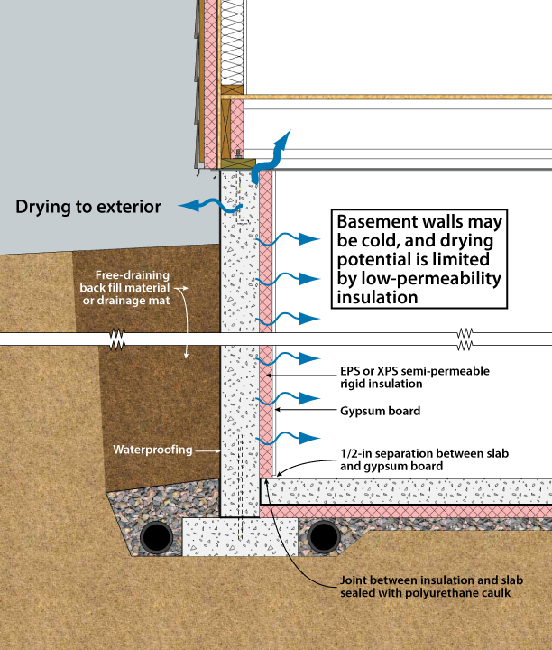
Figure 2-7. Basement with Interior Semi-Permeable XPS or EPS Insulation
There are two good approaches to interior basement insulation: rigid foam panels, and spray foam. Rigid foam systems consist of either expanded or extruded polystyrene foam board applied to the entire foundation wall, as shown in Figure 2-7 (BSC 2002). Spray foam applications typically involve spraying the entire foundation wall and typically the rim joist to an appropriate thickness. Additional unfaced batt insulation can be added to a frame wall built on the interior of the foam insulation, if desired. Foam plastic insulation materials are flammable, and must be protected from ignition. If no additional insulation is desired, wood furring strips can be attached over the foam and gypsum board may be attached to the furring strips. In all below-grade construction, non-paper faced gypsum board is recommended to reduce the risk of moisture-related damage. The gypsum board should be held at least a half inch above the basement floor to avoid wetting (Baechler et al. 2005). No vapor retarders, such as polyethylene, vinyl wallpaper, or oil-based paint should be used anywhere in the system to ensure drying to the interior.
It is possible to eliminate the use of gypsum board as an ignition barrier. This has been done by using foil-faced polyisocyanurate insulation panels, some of which are rated for exposure in basements and crawl spaces in some jurisdictions. Note however that the unperforated foil facing is completely vapor-impermeable, and very little drying will occur through it. Many jurisdictions will also allow high-density polyurethane foam to coat the rim and sill area (but not the entire wall) with no additional fire protection.
Interior insulation retrofits carry additional risks: capillary breaks may not be present between the foundation and the framing; insulating on the interior will tend to increase moisture accumulation in the framing. A capillary break may not be present between the footing and the wall, potentially increasing the presence of moisture due to capillary wicking. Since waterproofing and drainage systems are often not present or not working on older houses, bulk water penetration is possible. For description of a robust retrofit interior insulation strategy see Ueno (2011).
In addition to more conventional interior or exterior placement covered in this handbook, there are several systems that incorporate insulation into the construction of the concrete or masonry walls. These include (1) rigid foam plastic insulation cast within a concrete wall (Figure 2-5c), (2) polystyrene beads, granular insulation materials, or spray foam poured into the cavities of conventional masonry walls, (3) systems of concrete blocks with insulating foam inserts, (4) formed, interlocking rigid foam units that serve as a permanent, insulating form for cast-in-place concrete (insulated concrete forms, or ICFs, Figure 2-5d), and (5) masonry blocks made with polystyrene beads instead of aggregate in the concrete mixture, resulting in significantly higher R-values. However, the effectiveness of systems that insulate only a portion of the wall area should be evaluated closely because thermal bridges around the insulation can impact the total performance significantly.
Lastly, another technique for basement construction in new construction is to use pre-cast concrete foundation walls. Two types are acceptable. The first are concrete walls with built in footers that rest on an engineered gravel footing that allows the entire assembly to be drained. This means that as long as the panels are sealed correctly during construction, these walls will remain warm and dry. These walls are designed to be insulated on the exterior. The second are pre-cast concrete walls that come with one inch of rigid foam insulation attached to the interior. These walls are constructed to allow additional insulation to be installed between the stud bays and come with built in wood nailers to attach gypsum board or paneling (BSC 2002).
TERMITE AND WOOD DECAY CONTROL TECHNIQUES
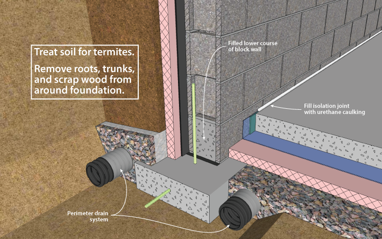
Figure 2-8F. Termite Control Techniques for Basements, Footing Detail
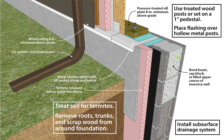
Figure 2-8S. Termite Control Techniques for Basements, Sill Detail
Techniques for controlling the entry of termites through residential foundations are advisable in much of the United States (see Figures 2-8F and 2-8S). The following recommendations apply where termites are a potential problem. Consult with local building officials and codes for further details.
Plastic foam and mineral wool insulation materials have no food value to termites, but they can provide protective cover and easy tunneling. Insulation installations can be detailed for ease of inspection, although often by sacrificing thermal efficiency.
In principle, termite shields offer protection, but should not be relied upon as a barrier. Termite shields are shown in this document as a component of exterior insulation systems. Their purpose is to force any insects ascending through the wall out to the exterior, where they can be seen. For this reason, termite shields must be continuous, and all seams must be sealed to prevent bypass by the insects.
These concerns over insulation and the unreliability of termite shields have led to the conclusion that soil treatment is the most effective technique to control termites with an insulated foundation. However, the restrictions on widely used termiticides may make this option either unavailable or cause the substitution of products that are more expensive and possibly less effective. This situation should encourage insulation techniques that enhance visual inspection and provide effective barriers to termites. For more information on termite mitigation techniques, see NAHB (2006).
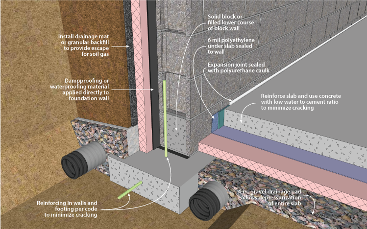
Figure 2-9F. Radon Control Techniques for Basements, Footing Detail
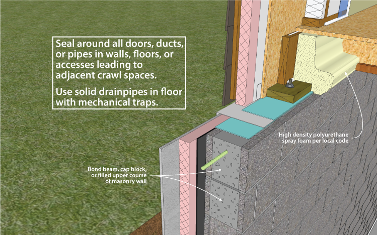
Figure 2-9S. Radon Control Techniques for Basements, Sill Detail
Construction techniques for minimizing radon infiltration into the basement are appropriate where there is a reasonable probability that radon may be present (see Figures 2-9s, 2-9f, and 2-10). To determine this, contact the state radon staff. General approaches to minimizing radon include (1) evacuating soil gas surrounding the basement, and (2) sealing joints, cracks, and penetrations in the foundation.
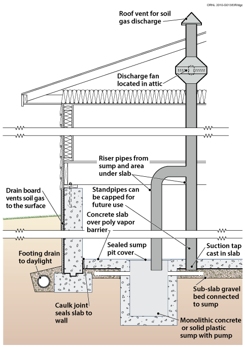
Figure 2-10. Soil Gas Collection and Discharge Techniques
The most effective way to limit radon and other soil gas entry is through the use of active soil depressurization (ASD). ASD works by lowering the air pressure in the soil relative to the indoors. Avoiding foundation openings to the soil, or sealing those openings, as well as limiting sources of indoor depressurization aid ASD systems. Sometimes a passive soil depressurization (PSD, with no fan) system is used. If post-occupancy radon testing indicates further radon reduction is desirable, a fan can be installed in the vent pipe (see Figure 2-10).
Subslab depressurization has proven to be an effective technique for reducing radon concentrations to acceptable levels, even in homes with extremely high concentrations (Dudney 1988). This technique lowers the pressure around the foundation envelope, causing the soil gas to be routed into a collection system, avoiding the inside spaces and discharging to the outdoors.
A foundation with good subsurface drainage already has a collection system. The underslab gravel drainage layer can be used to collect soil gas. It should be at least 4 inches thick, and of clean aggregate no less than 1/2 inch in diameter. The gravel should be covered with a 6-mil polyethylene radon and moisture retarder.
A 3- or 4-inch diameter PVC vent pipe should be routed from subslab gravel layer through the conditioned portion of the building and through the highest roof plane. The pipe should terminate below the slab with a “tee” fitting. To prevent clogging the pipe with gravel, ten-foot lengths of perforated draintile can be attached to the legs of the tee, and sealed at the ends. Alternately, the vent pipe can be connected to the perimeter drain system, as long as that system does not connect to the outdoor environment. Horizontal vent pipes could connect the vent stack through below grade walls to permeable areas beneath adjoining slabs. A single vent pipe is adequate for most houses with less than 2,500 square feet of slab area that also include a permeable subslab layer. The vent pipe is routed to the roof through plumbing chases, interior walls, or closets.
A PSD system requires the floor slab to be nearly airtight so that collection efforts are not short-circuited by drawing excessive room air down through the slab and into the system. Cracks, slab penetrations, and control joints must be sealed. Sump hole covers should be designed and installed to be airtight. Floor drains that discharge to the gravel beneath the slab should be avoided, but when used, should be fitted with a mechanical trap capable of providing an airtight seal.
Another potential short circuit can occur if the subdrainage system has a gravity discharge to an underground outfall. This discharge line may need to be provided with a mechanical seal. The subsurface drainage discharge line, if not run into a sealed sump, should be constructed with a solid-glued drainpipe that runs to daylight. The standpipe should be located on the opposite side from this drainage discharge.
While a properly installed passive soil depressurization (PSD) system may reduce indoor radon concentrations by about 50%, active soil depressurization (ASD) systems can reduce indoor radon concentrations by up to 99%. A PSD system is more limited in terms of vent pipe routing options, and is less forgiving of construction defects than ASD systems. Furthermore, in new construction, small ASD fans (25-40 watt) may be used with minimal energy impact. Active systems use quiet, in-line duct fans to draw gas from the soil. The fan should be located outside, and ideally above, the conditioned space so that any air leaks from the positive pressure side of the fan or vent stack are not in the living space. The fan should be oriented to prevent accumulation of condensed water in the fan housing. The ASD stack should be routed up through the building or an attached garage or carport, and extend twelve inches above the roof. It can also be carried out through the band joist and up along the outside of wall, to a point high enough so that there is no danger of the exhaust being redirected into the building through attic vents or other pathways. Because PSD systems rely on natural buoyancy to operate, a PSD stack must be routed through the conditioned portion of the home.
A fan capable of maintaining 0.2 inch of water suction under installation conditions is adequate for serving subslab collection systems for most houses (Labs 1988). This is often achieved with a 0.03 hp (25W), 160 cfm centrifugal fan (maximum capacity) capable of drawing up to 1 inch of water before stalling. Under field conditions of 0.2 inch of water, such a fan operates at about 80 cfm.
It is possible to test the suction of the subslab system by drilling a small (1/4-inch) hole in areas of the slab remote from the suction point, and measuring the suction through the hole using a micromanometer or inclined manometer. The goal of a subslab depressurization system is to create negative air pressure below the slab, relative to the air pressure in the adjacent interior space. A suction of 5 Pascals is considered satisfactory when the house is placed in a worst-case depressurization condition (i.e., house closed, all exhaust fans and devices operating, and with the HVAC system operating with interior doors shut). The hole must be sealed after the test.
PSD systems require near perfection in sealing of openings to the soil, since the system relies on a 3- or 4-inch pipe to vent more effectively than the entire house. Sealing openings to the soil is less critical for radon control with ASD systems, although it is highly desirable in order to limit the energy penalty associated with conditioned indoor air leaking into a depressurized subslab, and from there to the outdoors. ASD fans have service lives averaging about ten years, with a higher life expectancy if the fan is protected from the elements. Since an ASD system may be turned off by occupants, service switches are usually located in areas with limited access.
For more information visit the Building America Solution Center.

