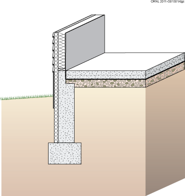
Figure 4-1. Slab-on-Grade Foundation with Exterior Insulation
STRUCTURAL DESIGN
The major structural components of a slab-on-grade foundation are the floor slab itself and either grade beams or foundation walls with footings at the perimeter of the slab (see Figures 4-2 and 4-3). In some cases additional footings (often a thickened slab) are necessary under bearing walls or columns in the center of the slab. Concrete slab-on-grade floors are generally designed to have sufficient strength to support floor loads without reinforcing when poured on undisturbed or compacted soil. The proper use of welded wire fabric and concrete with a low water/cement ratio can reduce shrinkage cracking, which is an important concern for appearance and can also aid radon infiltration control strategies.
Foundation walls are typically constructed of cast-in-place concrete or concrete masonry units. Foundation walls must be designed to resist vertical loads from the structure above and transfer these loads to the footing. Concrete spread footings must provide support beneath foundation walls and columns. Similarly, grade beams at the edge of the foundation support the superstructure above. Footings must be designed with adequate size to distribute the load to the soil. Freezing water beneath footings can heave, causing cracking and other structural problems. For this reason, footings must be placed beneath the maximum frost penetration depth unless founded on bedrock or proven non-frost susceptible soil or insulated to prevent frost penetration.
Where expansive soils are present or in areas of high seismic activity, special foundation construction techniques may be necessary. In these cases, consultation with local building officials and a structural engineer is recommended.
In general, moisture management schemes must control water in two states. First, since the soil in contact with the foundation and floor slab is always at 100% relative humidity, foundations must deal with water vapor that will tend to migrate toward the interior under most conditions. Second, liquid water must be kept from accumulating around and under the foundation. Liquid water comes from sources such as:
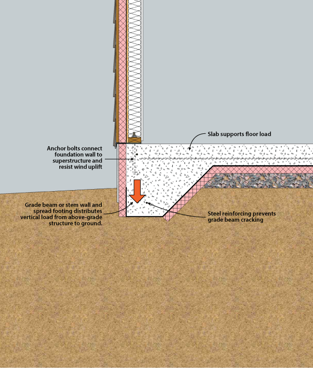
Figure 4-2. Structural System Components of Slab-on-Grade Foundation with Grade Beam
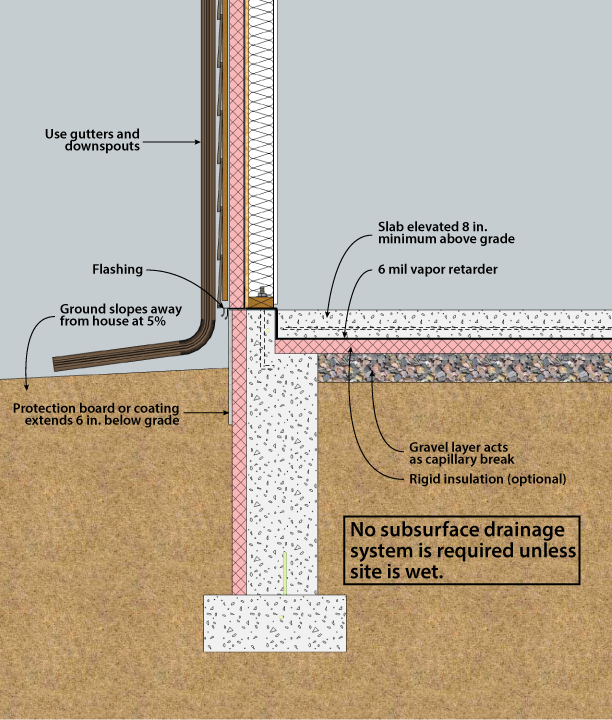
Figure 4-3. Drainage Techniques for Slab-on-Grade Foundations
Techniques for controlling the build-up and movement of moisture in the foundation are an essential component of the overall construction. Improper moisture management can lead to structural damage, damage to floor finishes, and mold growth, which can be very costly to repair and hazardous to one's health.
The following construction practices will prevent excess water in the form of liquid water and vapor from creating problems. This is done by using adequate drainage and by the use of vapor retarders. These guidelines and recommendations apply to thickened edge/monolithic slabs and stem wall foundations with independent above grade slab configurations (PATH 2006). These two slab-on-grade configurations are illustrated in Figures 4-2 and 4-3.
Since slab foundations do not enclose below-grade space, traditional waterproofing is often not required. However a continuous layer of capillary break / vapor retarder materials is required between the ground and the interior / above grade portions of the building. Depending on foundation design, this can include subslab vapor retarders, sill sealers, gaskets, waterproofing membranes, or other appropriate materials.
Rain water can be properly managed by using a well designed gutter and downspout system and by grading the ground around the foundation (6 inch drop in 10 feet) to channel water away from the foundation (Lstiburek 2006). The slab should also be elevated at least eight inches above grade to prevent water accumulating at the foundation (PATH 2006).
Since slab foundations place all the living space above grade, subgrade drainage is not always necessary. In some cases where seasonal surface water pooling may occur, or on sites with impermeable soils, it is recommended that a foundation drain be installed directly beside the bottom of the footing as recommended for basements and crawl spaces. The foundation drain assembly includes a filter fabric, gravel, and a perforated plastic drain pipe typically 4 inches in diameter. The drain runs to daylight or a sealed sump..
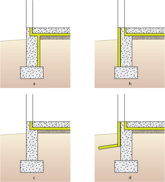
Figure 4-4. Potential Locations for Slab on Grade Insulation
Insulation is included in slab-on-grade construction for two purposes:
A wide variety of techniques can be employed to insulate slab-on-grade foundations (Figures 4-4 and 4-5). Good construction practice demands elevating the slab above grade by no less than 8 inches to isolate the wood framing from rain splash, soil dampness, and termites, and to keep the subslab drainage layer above the surrounding ground. The most intense heat transfer is through this small area of foundation wall above grade, so it requires special care in detailing and installation. Heat is also transferred between the slab and the soil, through which it migrates to the exterior ground surface and the air. Heat transfer with the soil is greatest at the edge, and diminishes rapidly with distance from it. In hot climates, direct coupling of the soil to the slab may moderate cooling loads, though at the risk of condensing moisture from the indoor air.
Both components of the slab heat transfer — at the edge and through the soil — must be considered in designing the insulation system. Insulation can be placed vertically outside the foundation wall or grade beam. This approach effectively insulates the exposed slab edge above grade and extends down to reduce heat flow from the floor slab to the ground surface outside the building. Vertical exterior insulation (Figure 4-5a) is the only method of reducing heat loss at the edge of an integral grade beam and slab foundation. For stemwall foundations, the major advantage of exterior insulation is that the interior joint between the slab and foundation may not need to be insulated, which simplifies construction. One drawback is that rigid insulation must be covered above grade with a protective board, coating, or flashing material. Another limitation is that the depth of the exterior insulation is controlled by the footing depth. However additional exterior insulation can be provided by extending insulation horizontally from the foundation wall. Since this approach can control frost penetration near the footing, it can be used to reduce footing depth requirements under certain circumstances (Figure 4-5a). This method is known as a “frost protected shallow foundation” (FPSF). A variation for unheated buildings is shown in Figure 4-5b. See NAHB (2004) for more information on this technique, which can substantially reduce the initial foundation construction cost.
Exterior insulation must be approved for below-grade use. Typically, three products are used below grade: extruded polystyrene, expanded polystyrene, and rigid mineral fiber panels. (Baechler et al. 2005). Extruded polystyrene (nominal R-5 per inch) is a common choice. Expanded polystyrene (nominal R-4 per inch) is less expensive, but it has a lower insulating value. Below-grade foams can be at risk for moisture accumulation under certain conditions. Experimental data indicate that this moisture accumulation may reduce the effective R-value as much as 35%-44%. Research conducted at Oak Ridge National Laboratories studied the moisture content and thermal resistance of foam insulation exposed below grade for fifteen years; moisture may continue to accumulate and degrade thermal performance beyond the fifteen-year timeframe of the study. This potential reduction should be accounted for when selecting the amount and type of insulation to be used (Kehrer, et al., 2012, Crandell 2010).
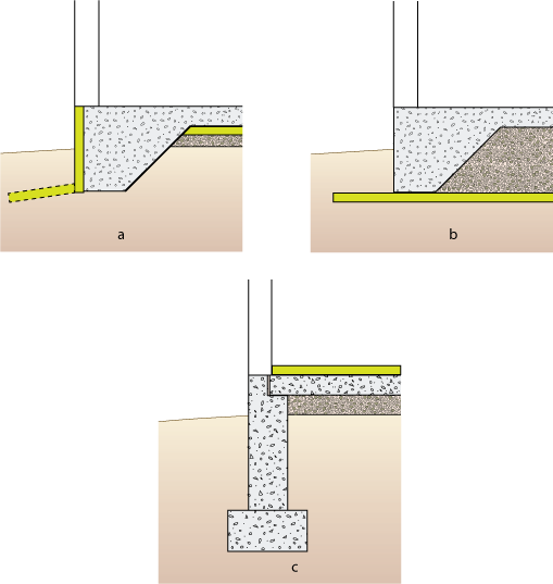
Figure 4-5. Potential Locations for Slab on Grade Insulation
Insulation also can be placed vertically on the interior of a stemwall or horizontally under the slab. In both cases, heat loss from the floor is reduced and the difficulty of placing and protecting exterior insulation is avoided. Interior vertical insulation is limited to the depth of the footing but underslab insulation is not limited in this respect. Usually the outer 2 to 4 feet of the slab perimeter is insulated but the entire floor may be insulated if desired. Remember that condensation control is an important consideration, along with heating energy use. It is essential to insulate the joint between the slab and the foundation wall whenever insulation is placed inside the foundation wall or under the slab. Otherwise, a significant amount of heat transfer occurs through the thermal bridge at the slab edge. The insulation is generally limited to no more than 1 inch in thickness at this point. Figure 4-4d shows insulation under the slab and at the slab edge to control the temperature of the slab, with exterior insulation placed vertically and horizontally to prevent frost penetration to the footing.
Another option for insulating a slab-on-grade foundation is to place insulation above the floor slab (Figure 4-5c). This may be the only option for retrofit applications. It can be appropriate for new construction as well, especially when wood is the desired floor finish. These techniques have critical details that must be followed to avoid moisture problems; full descriptions can be found in Lstiburek (2006).
Other specialty systems can be used for slab-on-grade stemwalls. These include insulated concrete forms (ICFs), post-tensioned slabs, and systems that place foam insulation between two layers of cast in place concrete.
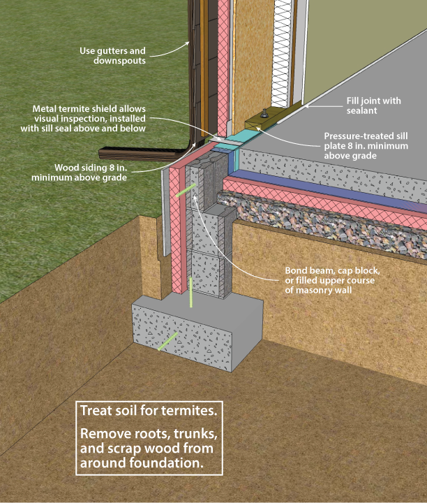
Figure 4-6. Slab-on-Grade Termite Control Techniques
TERMITE AND WOOD DECAY CONTROL TECHNIQUES
Techniques for controlling the entry of termites through residential foundations are necessary in much of the United States (see Figure 4-6). Consult with local building officials and codes for further details.
Plastic foam and mineral wool insulation materials have no food value to termites, but they can provide protective cover and easy tunneling. Insulation installations can be detailed for ease of inspection, although often by sacrificing thermal efficiency.
In principle, termite shields offer protection, but should not be relied upon as a barrier. Termite shields are shown in this document as a component of all slab-on-grade designs. Their purpose is to force any insects ascending through the wall out to the exterior, where they can be seen. For this reason, termite shields must be continuous, and all seams must be sealed to prevent bypass by the insects.
These concerns over insulation and the unreliability of termite shields have led to the conclusion that soil treatment is the most effective technique to control termites with an insulated foundation. However, the restrictions on widely used termiticides may make this option either unavailable or cause the substitution of products that are more expensive and possibly less effective. This situation should encourage insulation techniques that enhance visual inspection and provide effective barriers to termites. For more information on termite mitigation techniques, see NAHB (2006).
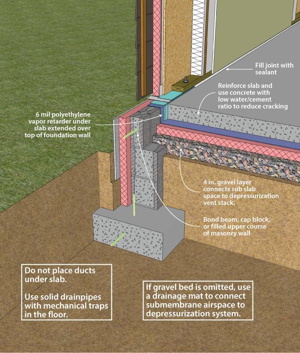
Figure 4-7. Slab-on-Grade Radon Control Techniques
Sealing the Slab
The following techniques for minimizing radon infiltration through a slab-on-grade foundation are appropriate, especially in moderate or high potential radon areas (zones 1 and 2) as designated by EPA (see Figures 4-7 and 4-8). To determine this, contact the state radon staff.
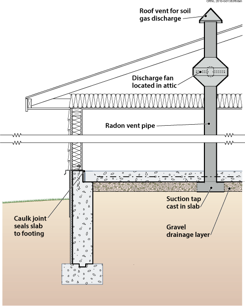
Figure 4-8. Soil Gas Collection and Discharge Techniques
The most effective way to limit radon and other soil gas entry is through the use of active soil depressurization (ASD). ASD works by lowering the air pressure in the soil relative to the indoors. Avoiding foundation openings to the soil, or sealing those openings, as well as limiting sources of indoor depressurization aid ASD systems. Sometimes a passive soil depressurization (PSD, with no fan) system is used. If post-occupancy radon testing indicates further radon reduction is desirable, a fan can be installed in the vent pipe (see Figure 4-8).
Subslab depressurization has proven to be an effective technique for reducing radon concentrations to acceptable levels, even in homes with extremely high concentrations (Dudney 1988). This technique lowers the pressure around the foundation envelope, causing the soil gas to be routed into a collection system, avoiding the inside spaces and discharging to the outdoors.
A foundation with good subsurface drainage already has a collection system. The underslab gravel drainage layer can be used to collect soil gas. It should be at least 4 inches thick, and of clean aggregate no less than 1/2 inch in diameter. The gravel should be covered with a 6-mil polyethylene radon and vapor retarder.
A 3- or 4-inch diameter PVC vent pipe should be routed from the subslab gravel layer through the conditioned portion of the building and through the highest roof plane. The pipe should terminate below the slab with a “tee” fitting. To prevent clogging the pipe with gravel, ten-foot lengths of perforated draintile can be attached to the legs of the tee, and sealed at the ends. Alternately, the vent pipe can be connected to a perimeter drain system, as long as that system does not connect to the outdoor environment. Horizontal vent pipes could connect the vent stack through below grade walls to permeable areas beneath adjoining slabs. A single vent pipe is adequate for most houses with less than 2,500 square feet of slab area that also include a permeable subslab layer. The vent pipe is routed to the roof through plumbing chases, interior walls, or closets.
A PSD system requires the floor slab to be nearly airtight so that collection efforts are not short-circuited by drawing excessive room air down through the slab and into the system. Cracks, slab penetrations, and control joints must be sealed. Floor drains that discharge to the gravel beneath the slab should be avoided, but when used, should be fitted with a mechanical trap capable of providing an airtight seal.
While a properly installed passive soil depressurization (PSD) system may reduce indoor radon concentrations by about 50%, active soil depressurization (ASD) systems can reduce indoor radon concentrations by up to 99%. A PSD system is more limited in terms of vent pipe routing options, and is less forgiving of construction defects than ASD systems. Furthermore, in new construction, small ASD fans (25-40 watt) may be used with minimal energy impact. Active systems use quiet, in-line duct fans to draw gas from the soil. The fan should be located outside, and ideally above, the conditioned space so that any air leaks from the positive pressure side of the fan or vent stack are not in the living space. The fan should be oriented to prevent accumulation of condensed water in the fan housing. The ASD stack should be routed up through the building or an attached garage or carport, and extend twelve inches above the roof. It can also be carried out through the band joist and up along the outside of wall, to a point high enough so that there is no danger of the exhaust being redirected into the building through attic vents or other pathways. Because PSD systems rely on natural buoyancy to operate, a PSD stack must be routed through the conditioned portion of the home.
A fan capable of maintaining 0.2 inch of water suction under installation conditions is adequate for serving subslab collection systems for most houses (Labs 1988). This is often achieved with a 0.03 hp (25W), 160 cfm centrifugal fan (maximum capacity) capable of drawing up to 1 inch of water before stalling. Under field conditions of 0.2 inch of water, such a fan operates at about 80 cfm.
It is possible to test the suction of the subslab system by drilling a small (1/4-inch) hole in areas of the slab remote from the suction point, and measuring the suction through the hole using a micromanometer or inclined manometer. The goal of a subslab depressurization system is to create negative air pressure below the slab, relative to the air pressure in the adjacent interior space. A suction of 5 Pascals is considered satisfactory when the house is placed in a worst-case depressurization condition (i.e., house closed, all exhaust fans and devices operating, and with the HVAC system operating with interior doors shut). The hole must be sealed after the test.
PSD systems require near perfection in sealing of openings to the soil, since the system relies on a 3- or 4-inch pipe to vent more effectively than the entire house. Sealing openings to the soil is less critical for radon control with ASD systems, although it is highly desirable in order to limit the energy penalty associated with conditioned indoor air leaking into a depressurized subslab, and from there to the outdoors. ASD fans have service lives averaging about ten years, with a higher life expectancy if the fan is protected from the elements. Since an ASD system may be turned off by occupants, service switches are usually located in areas with limited access.
For more information visit the Building America Solution Center.

