In this section several typical slab-on-grade sections are illustrated and described. Figures 4-9 through 4-11, and 4-15 show configurations with insulation on the exterior surface of the foundation. Figures 4-12 through 4-14 show variations where the slab is the primary location for insulation.
Included in this group of details are variations in construction systems, insulation location, and moisture management strategies.
The challenge at this stage of design is to develop integrated solutions that address all key considerations without significantly complicating the construction or increasing the cost. There is no one set of perfect solutions; recommended practices or details often represent compromises and trade-offs. No particular approach is considered superior in all cases. This section shows and describes a variety of reasonable alternatives. Individual circumstances will dictate final design choices.
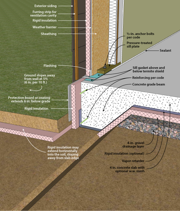
Figure 4-9. Slab-on-Grade with Integral Grade Beam with Exterior Insulation. Click here for an animation.
Figure 4-9 illustrates a slab-on-grade foundation with an integral grade beam. The rigid insulation is placed vertically on the exterior face of the grade beam. This insulation aligns with rigid foam sheathing that covers the framed walls above grade. Additional insulation may be placed horizontally around the foundation perimeter. This can reduce the required depth of the slab in colder climates. Subslab insulation is placed horizontally, and extends down the sloped sides of the grade beam.
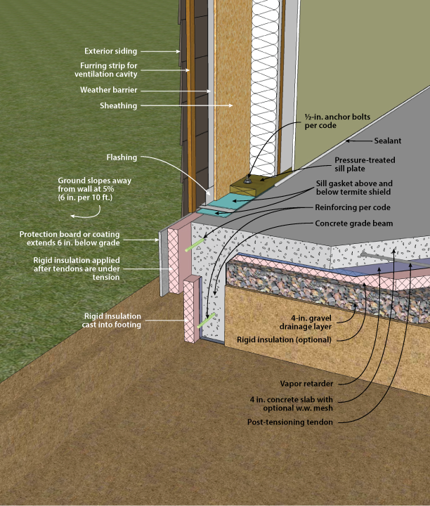
Figure 4-10. Post-Tensioned Slab-on-Grade with Exterior and Slab Insulation
Figure 4-10 shows an exterior insulation for a post-tensioned slab. The vapor retarder runs continuously around the footing. The lower piece of rigid insulation is placed in the footing form, and the vapor retarder is sealed to it. After the footing is poured, the footing can be partially backfilled. Then the post-tensioning tendons are placed under tension. The upper piece of foam can then be applied and covered with a protective material. See Lstiburek (2006) for more information on this application. Additional foam may be used on the inside vertical face of the stemwall.
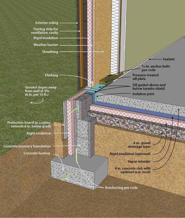
Figure 4-11. Slab-on-Grade with Concrete Masonry Stem Wall and Exterior Insulation
Figure 4-11 illustrates a slab-on-grade foundation with a masonry foundation wall. Rigid insulation is placed vertically on the exterior face of the foundation wall. This insulation aligns with rigid foam sheathing that covers the framed walls above grade. Moisture control is provided by a vapor retarder under the slab. This vapor retarder is is continued up and over the stem wall, and capped by sill sealer between the foundation and the bottom plate of the framed wall.
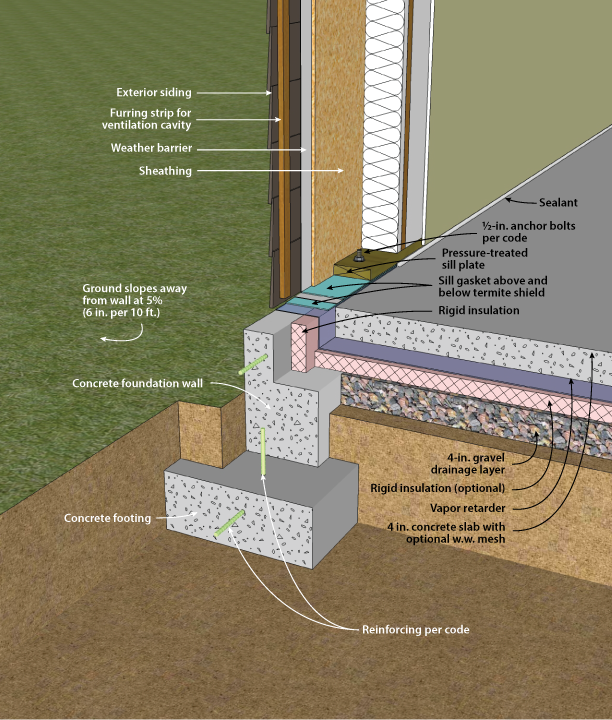
Figure 4-12. Slab-on-Grade with Concrete Stem Wall and Under Slab Insulation. Click here for an animation. Click here for an animation.
Figure 4-12 illustrates a slab-on-grade with a concrete foundation wall. Rigid insulation is placed horizontally under the slab perimeter and vertically in the joint at the slab edge. Moisture control is similar to figure 4-11, with the vapor retarder placed on top of the rigid insulation.
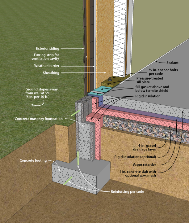
Figure 4-13. Slab-on-Grade with Masonry Stem Wall and Interior and Slab Insulation
Figure 4-13 illustrates a slab-on-grade foundation with a concrete masonry foundation wall. Rigid insulation is placed vertically on the interior face of the foundation wall and extends into the joint at the slab edge. This solution can employ insulation at the stem wall only, which isolates the slab from the exterior side of the foundation, but does not isolate it from the subslab grade. Insulation may be placed under the slab (as shown) for additional thermal or condensation control. This example shows a 2 x 6 above-grade wood frame wall with cavity insulation.
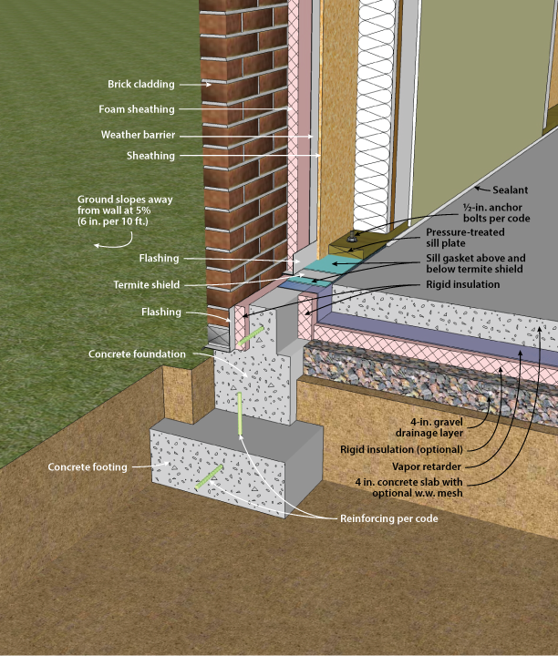
Figure 4-14. Slab-on-Grade with Concrete Stem Wall and Slab Insulation
Figure 4-14 illustrates a slab-on-grade with a concrete foundation wall. The wall has a brick ledge cast in. The interior face is cast with a ledge so that the interior vertical insulation can be concealed under the 2x6 framed wall. Rigid insulation is placed horizontally under the slab perimeter and vertically in the joint at the slab edge. Additionally, a layer of rigid foam is used between the framing and ventilation space behind the brick cladding. This technique can limit inward vapor movement when the sun shines on damp bricks.
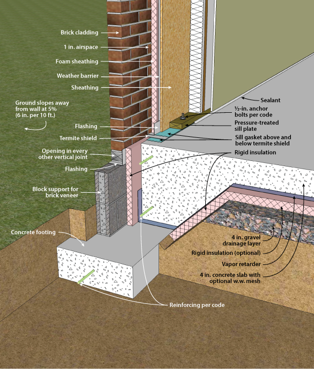
Figure 4-15. Slab-on-grade with Integral Grade Beam and Exterior and Slab Insulation
Figure 4-15 illustrates a slab-on-grade with an integral grade beam. The grade beam sits on a footing, which provides support for the brick cladding. Foam insulation runs on the inside face of the airspace behind the brick. The foundation insulation is in the same plane, and is applied to the slab edge below the termite shield down to the footing.

