
- Contents
- 1: Intro
- 2: Basement
- 3: Crawl Space
- 4: Slab-On-Grade
- Case Studies
- References
- Credits

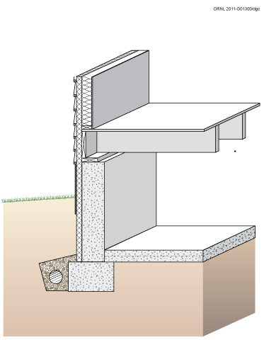
Figure 3-1. Concrete Crawl Space Wall with Exterior Insulation
VENTED VERSUS UNVENTED CRAWL SPACES
The principal perceived advantage of a vented crawl space over an unvented one is that venting may limit radon and moisture-related decay hazards by diluting the crawl space air. Additionally, providing a vented crawl space may make sense in flood-prone areas such as coastal zones subject to hurricanes. Venting can complement other moisture and radon control measures such as ground cover and proper drainage. However, although increased air flow in the crawl space may offer some dilution potential for ground source moisture and radon, it will not necessarily solve a serious problem. Vented crawl spaces are often provided with operable vents that can be closed to reduce winter heat losses, but also potentially increase radon infiltration. Although not their original purpose, the vents can also be closed in summer to keep out moist exterior air that can have a dew point above the crawl space temperature. This approach, however, requires a high level of informed occupant participation to be successful.
Unvented (conditioned) crawl spaces are generally preferred in most cases, except where flood risks are exceptionally high, as in coastal zones subject to hurricane flooding. The principal disadvantages of a vented crawl space over an unvented one are that (1) pipes and ducts must be sealed and insulated against heat loss (cooling loss in the summer) and freezing, (2) a larger area (the crawl space ceiling typically is larger than the area of the crawl space walls) usually must be insulated, which may increase the cost, (3) under hot humid conditions warm humid air circulated into the cool crawl space can cause excessive moisture levels in structural wood components (especially floor joists) that can cause mold and decay, and (4) an airtight, continuous thermal envelope at the crawl space ceiling is very difficult to achieve in practice. It is not necessary to vent a crawl space for moisture control if it is open to an adjacent basement, and venting is clearly incompatible with crawl spaces used as conditioned air distribution plenums. In fact, there are several advantages to designing crawl spaces as semi-conditioned zones. Duct and pipe insulation can be reduced, and the foundation is insulated at the crawl space perimeter instead of its ceiling. This usually requires less insulation, simplifies installation difficulties in some cases, and can be detailed to minimize condensation hazards.
Although unvented crawl spaces have been recommended, “except under severe moisture conditions,” by the University of Illinois’s Small Homes Council (Jones 1980), moisture problems in crawl spaces are common enough that many agencies are unwilling to endorse closing the vents year-round. Soil type and the groundwater level are key factors influencing moisture conditions. It should be recognized that a crawl space can be designed as a short basement (with slurry slab floor), and, having a higher floor level, is subject to less moisture hazard than a basement in most cases. Viewed in this way, the main distinction between unvented crawl spaces and basements is in the owner’s accessibility and likelihood of noticing moisture problems.
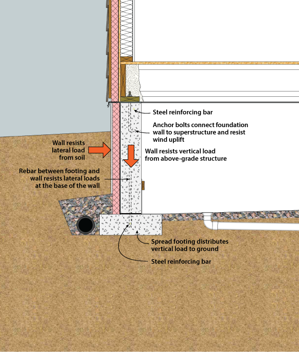
Figure 3-2. Structural System Components of a Crawl Space
STRUCTURAL DESIGN
The major structural components of a crawl space are the wall and the footing (see Figure 3-2). Crawl space walls are typically constructed of cast-in-place concrete, concrete masonry units, or alternative systems like insulated concrete forms (ICFs). Crawl space walls must resist any lateral loads from the soil and vertical loads from the structure above. The lateral loads on the wall depend on the height of the fill, the soil type and moisture content, and whether the building is located in an area of low or high seismic activity. Because of the large number of variables involved in foundation structural design, final determination of wall thickness, concrete strength, footing dimensions, and reinforcing should be made after consultation of locally-enforced building codes or design by a licensed structural engineer.
In place of a structural foundation wall and continuous spread footing, the structure can be supported on piers or piles with beams in between. These beams between piers support the structure above and transfer the load back to the piers.
Concrete spread footings provide support beneath concrete and masonry crawl space walls and/or columns. Footings must be designed with adequate size to distribute the load to the soil. Freezing water beneath footings can heave, causing cracking and other structural problems. For this reason, footings must be placed beneath the maximum frost penetration depth unless founded on bedrock or proven non-frost susceptible soil or insulated to prevent frost penetration. Since the interior temperature of a vented crawl space may be below freezing in cold climates, footings must be below the frost depth with respect to both interior and exterior grade unless otherwise protected.
Where expansive soils are present or in areas of high seismic activity, special foundation construction techniques may be necessary. In these cases, consultation with local building officials and a structural engineer is recommended.
While the crawl space is not meant to be living space (such as a basement), it is still very important to control the amount of moisture that can build up in that space. High levels of humidity at relatively low temperatures can cause condensation on different surfaces within the crawl space. This condensation can cause wooden support structures to rot, decreasing their structural integrity. Condensation and high levels of moisture also create an environment that is conducive to mold growth, which can have adverse effects on the health of the home’s inhabitants.
In general, moisture management schemes must control water in two states. First, since the soil in contact with the foundation wall is always at 100% relative humidity, foundation walls must deal with water vapor that will tend to migrate toward the interior under most conditions. Second, liquid water entry must be prevented. Liquid water can enter from sources such as:
There are two main configurations for crawl spaces: vented and unvented. The vented crawl space has historically been the most widely employed design. It works by allowing outside air to flow through the crawl space, thereby, in theory, removing the excess moisture and allowing it to dry (Davis et al. 2005). Unvented crawl spaces (also known as closed or conditioned) do not have vents to the outside and rely on limiting moisture intrusion from the soil, along with mechanical drying mechanisms such as air conditioning or a dehumidifier to prevent moisture build-up (Dastur et al. 2005). For both vented and unvented designs, there are common techniques that are used to limit the moisture content in the crawl space. These techniques include methods for blocking moisture sources by providing proper drainage, vapor retarders and air barriers. Additional methods for removing moisture build up in the crawl space are also employed.

Figure 3-3. Crawl Space Drainage: Crawl Space Floor At or Above Grade
The following construction practices will prevent excess water in the form of liquid and vapor from infiltrating the crawl space. These techniques are shown in Figures 3-3, 3-4, and 3-5.
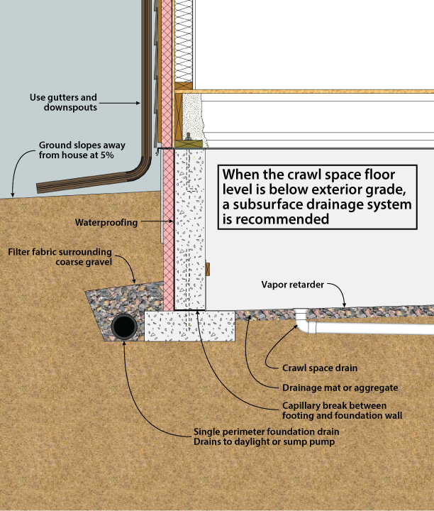
Figure 3-4. Crawl Space Drainage: Crawl Space Below Grade
Even after employing an effective crawl space drainage and vapor retarder system, it is still possible for moisture to find its way into the crawl space. In a vented crawl space, cooler temperatures may cause moisture in humid air to condense on the walls, ceiling, and on the ground. Another possible source of moisture accumulation inside the crawl space is pipe leaks. These sources can create pools of water that need to be evacuated. This can be achieved by grading the crawl space floor and by installing a drain or sump pump at the low point. (Dastur et al. 2005). It is important to complete the internal drainage system early in the construction to prevent moisture buildup that can occur before the roof is completed.
Concrete foundation walls contain water from when they were poured which needs to be dissipated by allowing them to dry. In cases where the majority of the wall is below grade, it can only dry to the interior. The insulation material and the wall covers placed on the walls during the construction of the crawl space act as vapor retarders, not allowing the walls to dry to the interior. For this reason, it is recommended that these wall coverings be installed near the end of construction to allow for as much drying of the concrete as possible (BSC 2006).
In unvented crawl spaces it is important not only to have an effective vapor retarder, but also to have a complete air barrier. For this reason, all gaps between the foundation wall and sill plate, sill plate and band joist, and band joist and subfloor should be sealed. All gaps and penetrations in the foundation wall also need to be adequately sealed. A tight air barrier will prevent the influx of humid outside air through air transport, creating an interior space that is independent of outside moisture conditions. To further separate the conditions in the crawl space from those of the outside, mechanical drying systems such as a stand-alone dehumidifier should be used (Dastur et al. 2005). Alternately, the ductwork system can include the crawl space in the supply / return cycle to effectively treat it as an interior space.
To further separate the conditions in the crawl space from those of the outside, mechanical drying systems such as a stand-alone dehumidifier should be used (Dastur et al. 2005).
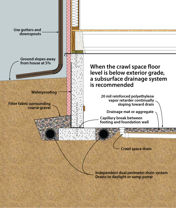
Figure 3-5. Crawl Space Drainage: Crawl Space Below Grade with Dual Drains
Although a crawl space foundation is not intended as living space, it is highly desirable to keep it dry. Good surface drainage is always recommended and, in many cases, subsurface drainage systems may be desirable. The goal of surface drainage is to keep water away from the foundation by sloping the ground surface and using gutters and downspouts for roof drainage.
Figure 3-3, 3-4, and 3-5 describe three different drainage techniques for crawl spaces. Figure 3-3 applies when the crawl space floor is flush with (or above) the surrounding grade. In most cases, this type of crawl space will not require perimeter drainage. On especially wet sites, or on sloping sites where part of the crawl space floor is below-grade, it may still be wise to install a perimeter drain system, described below. If the crawl space floor is above the top of the footing as shown, apply waterproofing on the interior face of the buried foundation wall to avoid capillary suction of water into the concrete.
Figure 3-4 and 3-5 describe foundation drain systems, which are recommended for all crawl spaces where the floor is below the level of the surrounding grade. On especially dry sites, it may be possible to eliminate the drainage system and not experience moisture problems. In most cases, a subsurface perimeter drainage system similar to that used for a basement is recommended (see Figures 3-4 and 3-5). Figure 3-5 describes the recommended best practice. It consists of two independent loops of perforated foundation drain, one inside the footing and one outside. These drain independently, either to daylight or to an internal sump. Figure 3-4 shows another option that is appropriate when site drainage conditions are good. There is no provision for drainage of the space inside the footings. Its single loop of foundation drain is on the outside of the footing, and drains to daylight or to an internal sump. It should be noted that the duct connection to the exterior of the footing can reduce the effectiveness of subslab depressurization radon mitigation systems by reducing the ability of the system to maintain sufficiently low pressures beneath the slab.
The final line of defense— waterproofing—is intended to keep out water that finds its way to the wall of the structure. First, it is important to distinguish between the need for dampproofing versus waterproofing. In most cases a dampproof coating covered by a 4-mil layer of polyethylene is recommended to reduce vapor and capillary draw transmission from the soil through the basement wall. A dampproof coating, however, is not effective in preventing water under hydrostatic pressure from entering through the wall. Waterproofing is recommended (1) on sites with anticipated water problems or poor drainage, (2) when the crawl space is intended for use as storage or houses mechanical equipment or (3) on any foundation built where intermittent hydrostatic pressure occurs against the basement wall due to rainfall, irrigation, or snow melt. Except on very dry sites, it is generally recommended to use waterproofing as a best practice. On sites where the crawl space floor could be below the water table, a slab-on-grade foundation is recommended.
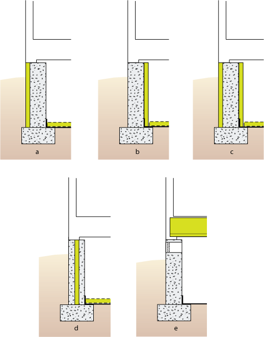
Figure 3-6. Potential Locations for Crawl Space Insulation
Another important factor to consider when managing moisture in a crawl space is the way it is to be insulated. Crawl spaces can be insulated at the exterior walls, or vented and insulated at the crawl space ceiling (Figure 3-6). Insulation not only plays a role in the thermal efficiency of a home but also in the way that moisture behaves. Cooler surfaces in a crawl space can cause moisture from the air to condense on the surfaces. For unvented crawl spaces, the best approach is to treat the crawl space as a short basement, placing insulation on the exterior or interior surface of the crawl space walls. Research has shown that closed crawl spaces with wall insulation have better energy and moisture performance than wall-vented crawl spaces with ceiling insulation (Dastur et al. 2005).
A key question in the design of an unvented crawl space is whether to place insulation inside or outside the wall. In terms of energy use, there is not a significant difference between the same amount of insulation applied to the exterior versus the interior of a concrete or masonry wall. However, the installation costs, ease of application, appearance, and various technical concerns can be quite different.
Rigid insulation placed on the exterior surface of a concrete (Figure 3-6a) or masonry wall has some advantages over interior placement in that it can provide continuous insulation with no thermal bridges, protect structural walls at moderate temperatures, and minimize moisture condensation problems (Figure 3-7). If the exterior insulation extends up over the rim joist and its R-value is high enough, the joists and sill plates can be left open to inspection from the interior for termites and decay. On the other hand, exterior insulation on the wall can be a path for termites and can prevent inspection of the wall from the exterior. If needed a termite barrier should be installed through the insulation where the sill plate rests on the foundation wall. This option is shown in all drawings that depict exterior crawl space foundation insulation. Vertical exterior insulation on a crawl space wall can extend as deep as the top of the footing and, if desired, be supplemented by extending the insulation horizontally from the face of the foundation wall. Insulation that is exposed above grade must be protected with a coating to prevent physical damage and degradation. Such coatings include fiber cement board, parging (stucco type material), treated plywood, or membrane material (Baechler et al. 2005).
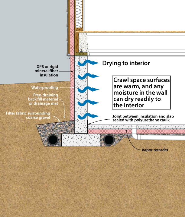
Figure 3-7. Crawl Space with Exterior Insulation
Exterior wall insulation must be approved for below-grade use. Typically, three products are used below grade: extruded polystyrene, expanded polystyrene, and rigid mineral fiber panels. (Baechler et al. 2005). Extruded polystyrene (nominal R-5 per inch) is a common choice. Expanded polystyrene (nominal R-4 per inch) is less expensive, but it has a lower insulating value. Below-grade foams can be at risk for moisture accumulation under certain conditions. Experimental data indicate that this moisture accumulation may reduce the effective R-value as much as 35%-44%. Research conducted at Oak Ridge National Laboratories studied the moisture content and thermal resistance of foam insulation exposed below grade for fifteen years; moisture may continue to accumulate and degrade thermal performance beyond the fifteen-year time frame of the study. This potential reduction should be accounted for when selecting the amount and type of insulation to be used (Kehrer, et al., 2012, Crandell 2010).
Rigid fiberglass and rigid mineral wool panels (R-4 per inch) do not insulate as well as extruded polystyrene, but are the only insulations that can provide a drainage space for foundation walls because of their porous structure. Use of these materials as a drainage space only works if effective footing perimeter drains are present.
Interior crawl space wall insulation (Figure 3-6b) is more common than exterior, primarily because it is less expensive since no protective covering is required, and can present a reduced hazard of termite infestation. On the other hand, interior wall insulation may be considered less desirable than exterior insulation because it (1) increases the exposure of the wall to thermal stress and freezing, (2) may increase the likelihood of condensation on sill plates, band joists, and joist ends, (3) often results in some thermal bridges through framing members, and (4) usually requires installation of a flame resistant cover. Interior insulation is not recommended on non-core filled masonry block walls, due to an increased risk of moisture accumulation within the assembly. In addition, interior insulation should not be used if a positive capillary break is not present between the top of the foundation wall and wood framing system due to the potential for moisture accumulation in wood framing materials.
Materials that are resistant to moisture damage are recommended for use in contact with concrete foundation components. Rigid foam plastic or high-density spray polyurethane foam are the two materials recommended to insulate the interior side of walls in unvented crawl spaces (Figure 3-8). In areas not prone to termite infestation, rigid foam should be installed and sealed at the rim joist to prevent entry of moist air into the wood structural components. This air barrier is especially critical in cold climates, and when exterior insulation is not installed. Batt insulation should only be used at the rim joist where access is required for termite inspections. Expanded or extruded polystyrene rigid foam insulation should be used to cover the walls and be attached with mechanical fasteners. A three-inch wicking gap should be left between the wall insulation and the ground, and a three inch termite inspection gap or continuous termite shield should be present at the top of the wall and the sill plate (Marshall 2008). An ignition barrier or fire barrier will likely be required, based on code jurisdiction and occupancy.
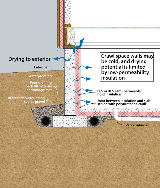
Figure 3-8. Crawl Space Interior Insulation with EPS or XPS Semi-Permeable Insulation on Inside Wall
It is possible to eliminate the ignition barrier requirement. This has been done by using foil-faced polyisocyanurate insulation panels, which are rated for exposure in basements and crawl spaces in some jurisdictions. Note however that the unperforated foil facing is completely vapor-impermeable, and very little drying will occur through it. Many jurisdictions will also allow high-density polyurethane foam to coat the rim and sill area (but not the entire wall) with no additional fire protection.
Interior insulation retrofits carry additional risks: capillary breaks may not be present, either at the top of the wall or between the foundation and the framing; insulating on the interior will tend to increase moisture accumulation in the framing in that case. A capillary break may not be present between the footing and the wall, potentially increasing the presence of moisture due to capillary wicking. Since waterproofing and drainage systems are often not present or not working on older houses, bulk water penetration is possible. For description of a robust retrofit interior insulation strategy see Ueno (2011).
Insulation placed horizontally around the crawl space floor perimeter can provide additional thermal protection for sealed crawl spaces with interior or exterior insulation on the foundation walls. However, it may also create additional paths for termite entry. In cold climates, insulation of the entire floor area to prevent heat loss may be desirable.
In a vented crawl space, the insulation is always located in the ceiling (Figures 3-6e and 3-9). There are two recommended approaches to crawl space ceiling insulation:
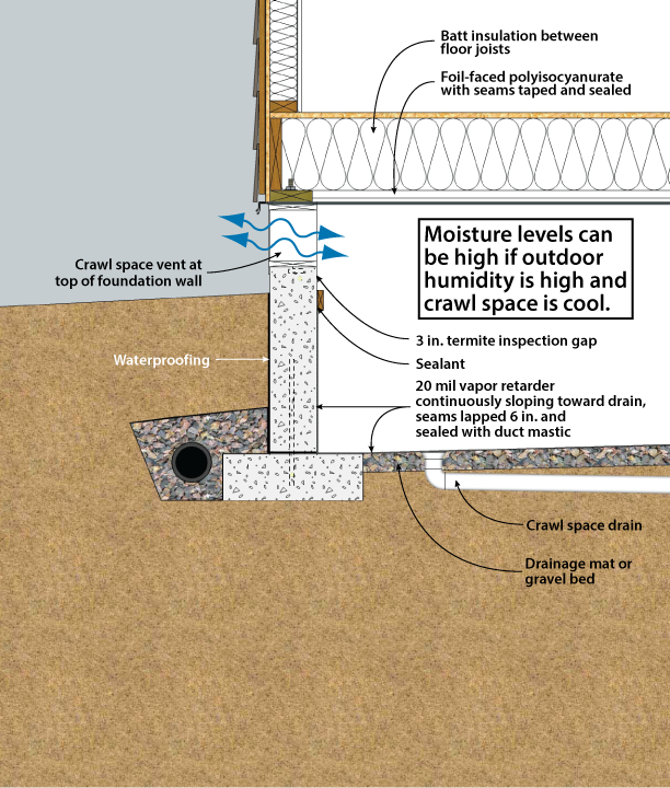
Figure 3-9. Vented Crawl Space with Insulation in the Ceiling
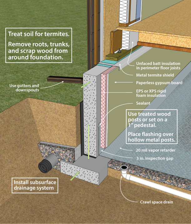
Figure 3-10. Unvented Crawl Space with Interior Insulation - Designed for Termite Resistance (Heavily Infested Areas)
These systems are the only ones capable of preventing mold and decay due to high humidity conditions that may occur in the crawl space in most climates (Lstiburek 2008). Impermeable floor finishes like vinyl flooring and some types of ceramic tile must be avoided to allow the floor to dry upward into the home.
In addition to more conventional interior or exterior placement covered in this handbook, there are several systems that incorporate insulation into the construction of the concrete or masonry walls. These include (1) rigid foam plastic insulation cast within concrete walls, (2) polystyrene beads or granular insulation materials poured into the cavities of conventional masonry walls, (3) systems of concrete blocks with insulating foam inserts, (4) formed, interlocking rigid foam units that serve as a permanent insulating form for cast-in-place concrete, and (5) masonry blocks made with polystyrene beads instead of aggregate in the concrete mixture, resulting in significantly higher R-values. However, the effectiveness of systems that insulate only a portion of the wall area should be evaluated closely because thermal bridges around the insulation can impact the total performance significantly.
TERMITE AND WOOD DECAY CONTROL TECHNIQUES
Techniques for controlling the entry of termites through residential foundations are advisable in much of the United States (see Figures 3-10 and 3-11). Figure 3-10 shows an example for areas with a high likelihood of termite infestation; Figure 3-11 shows an assembly for lower-risk parts of the country. The following recommendations apply where termites are a potential problem. Consult with local building officials and codes for further details.
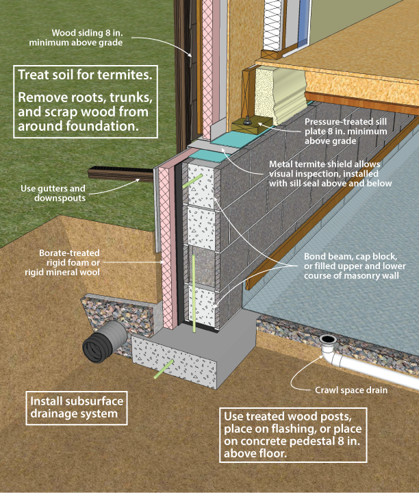
Figure 3-11. Unvented Concrete Masonry Unit Crawl Space with Exterior Insulation - Designed for Termite Resistance (Moderately Infested Areas)
Plastic foam and batt insulation materials have no food value to termites, but they can provide protective cover and easy tunnelling. Insulation installations can be detailed for ease of inspection, although often by sacrificing thermal efficiency.
In principle, termite shields offer protection, but should not be relied upon as a barrier. Termite shields are shown in this document as a component of exterior insulation systems. Their purpose is to force any insects ascending through the wall out to the exterior, where they can be seen. For this reason, termite shields must be continuous, and all seams must be sealed to prevent bypass by the insects.
These concerns over insulation and the unreliability of termite shields have led to the conclusion that soil treatment is the most effective technique to control termites with an insulated foundation. However, the restrictions on some traditionally used termiticides may make this option either unavailable or cause the substitution of products that are more expensive and possibly less effective. This situation should encourage insulation techniques that enhance visual inspection and provide effective barriers to termites. For more information on termite mitigation techniques, see NAHB (2006).
Construction techniques for minimizing radon infiltration into a crawl space are appropriate if there is a reasonable probability that radon is present. To determine this, contact the state radon staff.
Figure 3-12 shows an example for a vented crawl space; Figure 3-13 shows a vented example. General approaches to minimizing radon include (1) evacuating soil gas surrounding the basement, (2) sealing joints, cracks, and penetrations in the foundation, and (3) venting the crawl space while creating a continuous air barrier at the crawl space ceiling.
For ventilated crawl spaces
For unvented crawl spaces
The most effective way to limit radon and other soil gas entry is through the use of active soil depressurization (ASD). ASD works by lowering the air pressure in the soil relative to the indoors. Avoiding foundation openings to the soil, or sealing those openings, as well as limiting sources of indoor depressurization aid ASD systems. Sometimes a passive soil depressurization (PSD, with no fan) system is used. If post-occupancy radon testing indicates further radon reduction is desirable, a fan can be installed in the vent pipe (see Figure 3-13).
Subslab (or sub-membrane) depressurization has proven to be an effective technique for reducing radon concentrations to acceptable levels, even in homes with extremely high concentrations (Dudney 1988). This technique lowers the pressure around the foundation envelope, causing the soil gas to be routed into a collection system, avoiding the inside spaces and discharging to the outdoors.
A foundation with good subsurface drainage already has a collection system. The subslab (or sub-membrane) gravel drainage layer can be used to collect soil gas. It should be at least 4 inches thick, and of clean aggregate no less than 1/2 inch in diameter. The gravel should be covered with a 6-mil polyethylene radon and moisture retarder.
A 3- or 4-inch diameter PVC vent pipe should be routed from the gravel layer through the conditioned portion of the building and through the highest roof plane. The pipe should terminate below the slab or membrane with a “tee” fitting. To prevent clogging the pipe with gravel, ten-foot lengths of perforated draintile can be attached to the legs of the tee, and sealed at the ends. Alternately, the vent pipe can be connected to the perimeter drain system, as long as that system does not connect to the outdoor environment. Horizontal vent pipes could connect the vent stack through below grade walls to permeable areas beneath adjoining slabs or membranes. A single vent pipe is adequate for most houses with less than 2,500 square feet of floor area that also include a permeable subslab layer. The vent pipe is routed to the roof through plumbing chases, interior walls, or closets.
A PSD system requires the floor to be nearly airtight so that collection efforts are not short-circuited by drawing excessive room air down through the air barrier and into the system. Cracks, penetrations, and control joints must be sealed. Sump hole covers should be designed and installed to be airtight. Floor drains that discharge to the gravel beneath the slab should be avoided, but when used, should be fitted with a mechanical trap capable of providing an airtight seal.
Another potential short circuit can occur if the subdrainage system has a gravity discharge to an underground outfall. This discharge line may need to be provided with a mechanical seal. The subsurface drainage discharge line, if not run into a sealed sump, should be constructed with a solid-glued drainpipe that runs to daylight. The standpipe should be located on the opposite side from this drainage discharge.
While a properly installed passive soil depressurization (PSD) system may reduce indoor radon concentrations by about 50%, active soil depressurization (ASD) systems can reduce indoor radon concentrations by up to 99%. A PSD system is more limited in terms of vent pipe routing options, and is less forgiving of construction defects than ASD systems. Furthermore, in new construction, small ASD fans (25-40 watt) may be used with minimal energy impact. Active systems use quiet, in-line duct fans to draw gas from the soil. The fan should be located outside, and ideally above, the conditioned space so that any air leaks from the positive pressure side of the fan or vent stack are not in the living space. The fan should be oriented to prevent accumulation of condensed water in the fan housing. The ASD stack should be routed up through the building or an attached garage or carport, and extend twelve inches above the roof. It can also be carried out through the band joist and up along the outside of wall, to a point high enough so that there is no danger of the exhaust being redirected into the building through attic vents or other pathways. Because PSD systems rely on natural buoyancy to operate, a PSD stack must be routed through the conditioned portion of the home.
A fan capable of maintaining 0.2 inch of water suction under installation conditions is adequate for serving subslab collection systems for most houses (Labs 1988). This is often achieved with a 0.03 hp (25W), 160 cfm centrifugal fan (maximum capacity) capable of drawing up to 1 inch of water before stalling. Under field conditions of 0.2 inch of water, such a fan operates at about 80 cfm.
PSD systems require near perfection in sealing of openings to the soil, since the system relies on a 3- or 4-inch pipe to vent more effectively than the entire house. Sealing openings to the soil is less critical for radon control with ASD systems, although it is highly desirable in order to limit the energy penalty associated with conditioned indoor air leaking into a depressurized subslab, and from there to the outdoors. ASD fans have service lives averaging about ten years, with a higher life expectancy if the fan is protected from the elements. Since an ASD system may be turned off by occupants, service switches are usually located in areas with limited access.
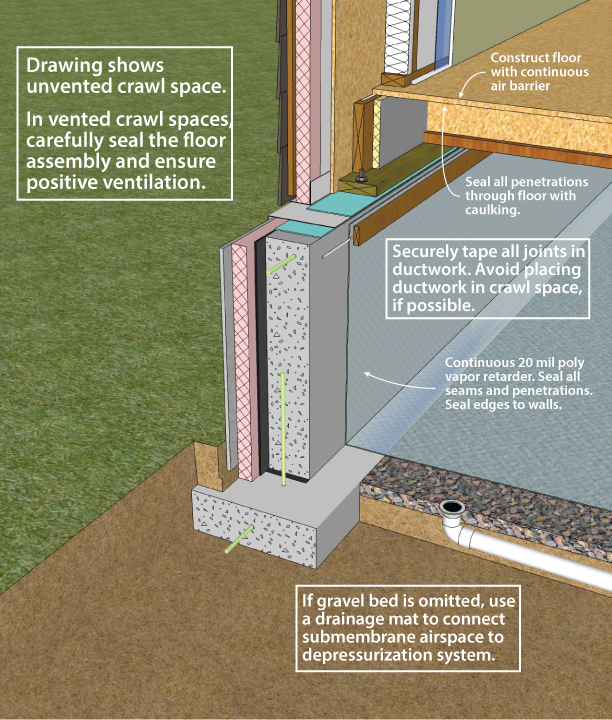
Figure 3-12. Crawl Space Radon Control Techniques
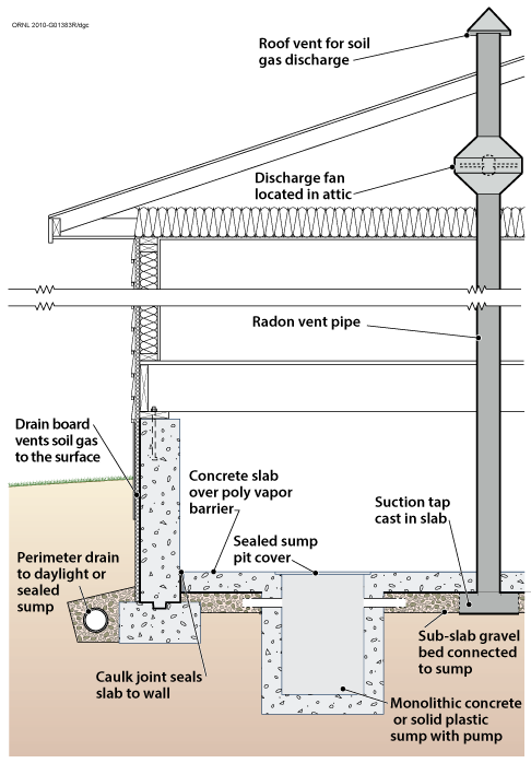
Figure 3-13. Soil Gas Collection and Discharge Techniques
For more information visit the Building America Solution Center.